I’ve created my first grid beam using the grid beam jig I posted about. It took me about a half an hour to cut beam holes in an 8 foot beam. Like others, I’m curious if the number of holes will compromise the beam…
Only 5 more to cut.
January 22nd, 2009 § Comments Off on First Grid Beam § permalink
I’ve created my first grid beam using the grid beam jig I posted about. It took me about a half an hour to cut beam holes in an 8 foot beam. Like others, I’m curious if the number of holes will compromise the beam…
Only 5 more to cut.
January 12th, 2009 § Comments Off on Arduino for TextMate posted (beta) § permalink
I’ve added a page for the Arduino for TextMate plugin. Download from the dedicated page.
January 11th, 2009 § Comments Off on When we last left our hero… § permalink
The problem with multitasking is that your time is divided amongst all the projects you have going on. Not only divided, but context switching has overhead. Because of this, and the limited shop time, I haven’t made much progress on any one area to warrant separate posts, so I’ll recap.

The Cool Tools blog had a recommendation for the Dyna-Glo pro heater. Their usage was similar to mine, so I decided to try it. I have to say – while it heats up the place in no time, it is loud and smelly. But the garage is now usable until I can insulate it and install something more permanent… (Although my father says “There is nothing more permanent than that which is temporary”)
At Maker Faire last year, I came across a neat display about Grid Beam. Basically this is a large scale wood erector set which involves 2×2 sticks of standard lengths, with a repeating hole pattern. These beams are joined using furniture connector bolts. By joining 3 beams together, you create a very strong ‘tri’-joint, which not only is self squaring, but creates a very rigid body. In fact, it seemed more rigid than the plastic and aluminum joints I currently use. Could I use a wood frame for the cartesian bot?
A book was released a few months ago; Half of which is an anthology of grid beaming, the other half goes into a little detail about assembly. You can get it from New Society publishers:Â

Using the lathe and mill has been slowly destroying my detail bench, where I do the electronics work and debugging. Task switching between metal work and detail work also slows down the whole process, so I decided to build a ‘dirty’ bench for the metal and wood work. It seemed like a perfect opportunity to try out Grid Beam building techniques.
My first foray into Grid beam stick construction were failures. There is no margin for error while cutting the holes, as errors propagate down the stick pulling them out of square very quickly. In order to drill accurate holes, I built a jig:
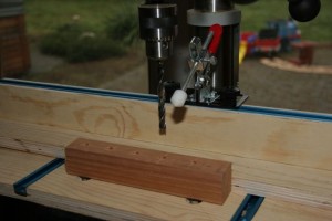
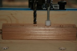
This is mostly a standard drill press jig. The main difference is in the holder – there is a custom delrin tapered plunger, which aligns and holds the beam prior to drilling. I’ve only drilled these sample beams for testing, so we’ll see how the hold thing goes together. I’ll post separately on this progress.
The arduino plugin for textmate has been taking much more time than it should. I’ve almost completely rewritten it in order to clean up the code, refactor based on ‘learnings’ about Cocoa, add multiple Arduino support, and allow the serial monitor to stick around while compiling and uploading. Many of the issues I’ve encountered were specific to TextMate (such as NSConnection issues), and some Leopard problems (NSConnection doesn’t like being created on two different threads). However, I’m tracking down the last issue (If you shutdown the serial monitor, you cannot restart it without restarting textmate. NSConnection doesn’t seem to have a way of saying is the server still alive). Expect a beta by end of the weekend.
I had worked on a design and implementation of Arduino design patterns which I will leverage in the Refactor. However, I hit a bug which doesn’t reproduce on the desktop test client, so I believe it is a specific problem with the Libc on the Arduino. That project was put on hold until I got the hardware debugger. Â I have it now, and it will be the first thing I work on after I release the new Arduino plugin.
With Shop time limited, this has bubbled down the list. Since my implementation depends on the Firmware refactor, it didn’t seem a high priority.
The Prometheus Fusion Perfection blog has developed a laser cut Herk extruder. It looks VERY sweet:
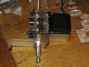
(If that person emails me their address, I’ll send a milled stainless steel barrel and extruder head.)
December 21st, 2008 § Comments Off on Laser cut Hercules Extruder § permalink
The Prometheus Fusion perfection blog has started working on a Laser cut Hercules Extruder. It looks pretty cool. I hope that the plastic can withstand the pinch forces involved with this. Keep an eye on it.Â
(I’d love to give credit to the author of it, want to send me your name? I couldn’t find it on your blog).
December 20th, 2008 § 4 comments § permalink
My workshop is in the garage – an uninsulated and unheated area. Currently the workshop is too cold to work comfortably or safely (I don’t want to get wrapped up in the lathe while wearing a ski jacket).
I’ve been looking into an electric heating and cooling solution. I haven’t found anything that can cover the whole workshop area of about 1,000sft. Most portable heating and air conditioning units top out at about 400 sqft. Either I need to partition the area, or look into something that will work over the whole area – maybe a heat pump for a small house or condo. It would also be nice if I can wall mount it, so I don’t take shop floor space…Â
Got any suggestions?
November 28th, 2008 § Comments Off on Pillars of Hercules § permalink
Here’s an updated Sketchup (for the new version 7) for the Hercules extruder.
The compact design of this extruder lends itself to stacking. By stacking two extruders, you can print with multiple materials. Why would you need two materials? A printed object at the very least needs a ‘raft’ – a lower fidelity flat area to which the object prints.
The first layer is in contact with the elevation system, which is of a different material than the object. This causes the first layer to behave unpredictably. Further layers become more consistent and allow higher fidelity strands to be laid. Objects with overhangs also need support material. In order to separate the support and raft material from the final object, you can print with different materials such as HDPE for the raft and ABS for the object. You could theoretically use two different temperatures for the raft and object materials.
I call this stacked extruder Pillars of Hercules
Here’s the sketchup of the Pillars of Hercules extruder
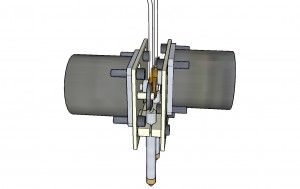
(I have no intention of building this anytime soon, it was just a fun exercise while crashed on the couch sick as a dog).
November 28th, 2008 § Comments Off on Tetrix available for pre-order! § permalink
Saw this kit at Make Faire in May – Metal Technix. Plastic gear trains have their limits, I can’t wait to see what people build with this stuff. The cool thing about this metal kit is the technix connectors which allow you to interface with the plastic lego components.
November 22nd, 2008 § Comments Off on Arduino for TextMate 2.0 (coming soon) § permalink
I’ve been working on an update to the ‘microcontroller’ plugin for TextMate. I’m putting the finishing touches on the release, and want it to bake. So far, it has the following changes:
Further, I’ll be creating a top level page for the plugin, and maybe releasing an ANSI graphics update to the arduino sources – allowing the arduino to provide rich graphics via the console.
November 19th, 2008 § Comments Off on Herk Extruder 1.1 § permalink
After accidentally destroying the motor controller and motor, I needed to rebuild the extruder. This is the result:

After the failure of the captured gear drive, I went back to the original pinched pulley mechanism – upgraded to the larger higher torque motor. One of the things I wanted to enable with this mechanism were:
I achieved the first point by making the tension pulley mounted directly to the backplane. The motor itself adjusts horizontally opposed to the tension pulley. This arrangement also allows me to test larger drive pulleys.
The barrel needs to adjust horizontally to match up with the center point of the pinch pulley mechanism as I test different sizes. I also wanted to adjust vertically to close the gap between the barrel top and the pulley pinch point.
The remaining plate is used for mounting to the cross slide, and enables me to implement a dovetail mount at a later date.
Now that the machining is done, I’ll wire it up. Additionally, I’ve been working on the software to drive it. (FYI: New TextMate microcontroller plugin drop is coming, with lots of new features and bug fixes)
(Please ignore the machining errors – still learning how to mill)
November 11th, 2008 § 1 comment § permalink
Developing the skills to build the captured gear drive took much longer than I had anticipated. When I began the development, I was new to machining, and had never cut a gear before.
The capture gears were difficult to machine. I stack cut the gears using a 24 pitch involute cutter on a 1.08″ blank. I then used a .125″ ball mill and milled a slot into each gear, then parted on the lathe. The parting was fairly problematic as the gear teeth caused too much chatter and ended up binding frequently.
I’m going to say that the captured gear drive experiment was a failure. The main failure is the difficulty in creating the specialized components, and getting the slot to the correct depth to enable the gears to mesh, as well as gripping the cord correctly.
I’m not convinced that the gear drive is better than the direct pulley drive.